Software & Hardware Integrated Prototyping for Beginners
A step-by-step guide to getting started with Arduino & ProtoPie.

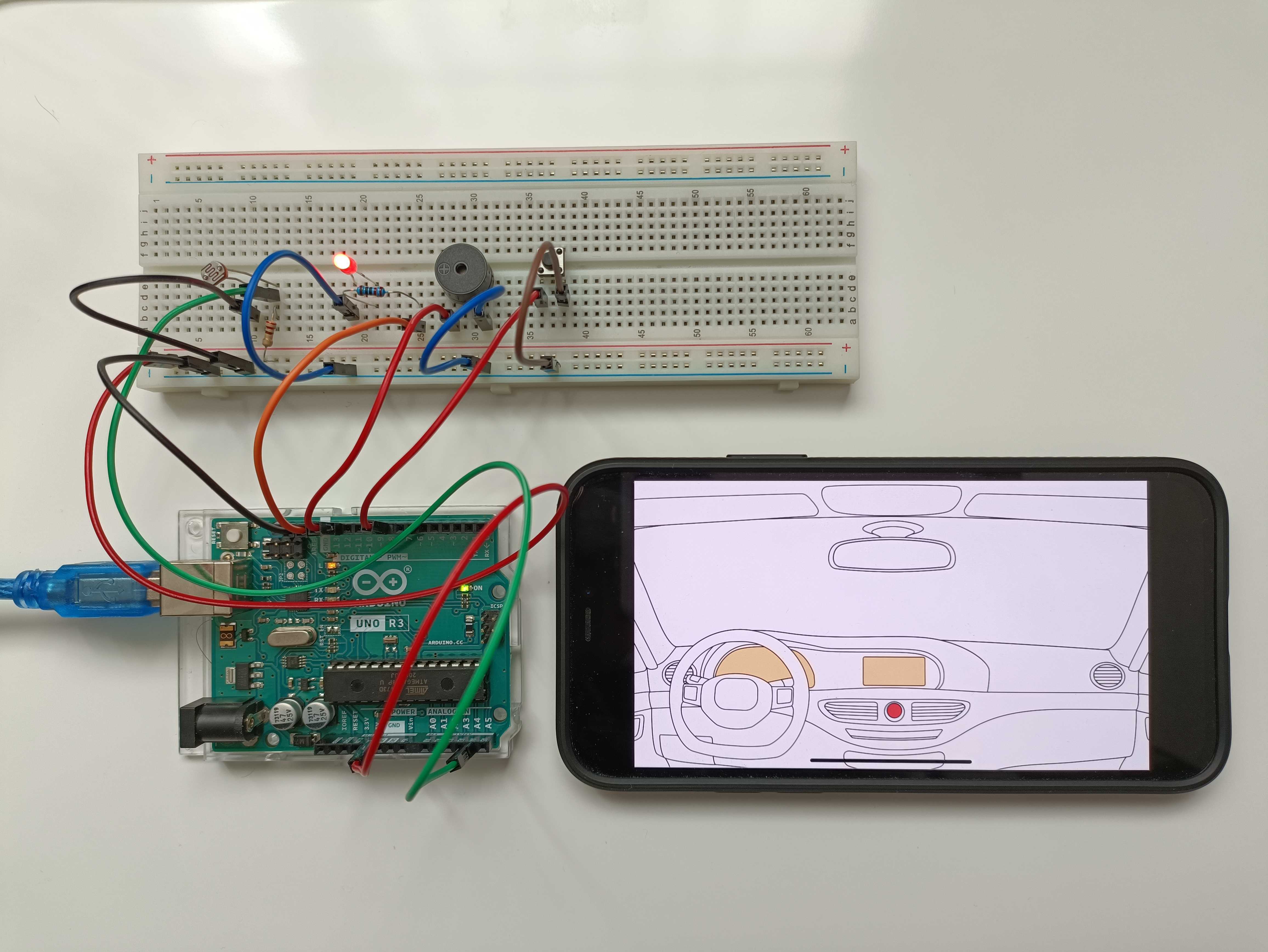
Digital transformation left its mark on all companies across the world, from Fortune 500 titans to that one small, emerging startup in your own backyard. As a result, over the last few years, the boundaries between software and hardware have arguably become blurrier than ever before.
Tech giants like Google and Amazon, traditionally classified as “software companies”, have begun creating their own hardware and software products, e.g. Google Nest and Amazon Alexa. Apple embodies this blended approach, acting as the textbook example of a company that has found the perfect balance between hardware and software.
But whether a product is hardware or software-based, or both, it still has to go through the same litmus test: multiple iterations of prototyping. Only those products that undergo this type of rigorous examination and validation—i.e., are made into realistic, interactive prototypes before being launched—will be a success with end-users.
Industrial designers have to prototype dynamic and flexible content that appears on a display. Software designers, on the other hand, might be required to prototype various pieces of hardware that are connected to digital content.
This is easier said than done. In fact, with IoT playing an increasingly large role in our day-to-day lives, this challenge is only increasing. Companies in the automotive and household appliance industries have been grappling with this pain point for many years now, and others will soon follow.
In this article, I will help you get started with creating your first software and hardware-integrated prototype.
Create magic with Arduino & ProtoPie
Makers love Arduino. Its gradual learning curve helps users get to grips with writing code, while its active community regularly shares inspirational examples of products that its makers have created.
However, using Arduino in conjunction with software prototypes (i.e. a display running a prototype that users interact with) can be a complex and overwhelming process.
Let's demonstrate how you can easily do this using ProtoPie. ProtoPie has 3 core elements, Studio, Player and Cloud, and 1 extension, Connect. But what do they all do?
- ProtoPie Studio is for creating interactions.
- ProtoPie Player is for running prototypes on smart devices.
- ProtoPie Cloud is for storing your prototypes online and collaborating with teams.
- ProtoPie Connect is for running prototypes simultaneously across multiple devices, displays, and pieces of hardware.
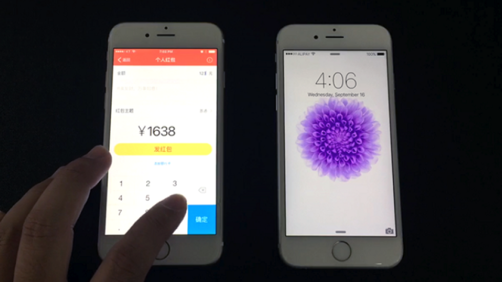
With ProtoPie Connect, your prototypes can send signals to—and receive signals from—Arduino. This means that you can have software prototypes communicate with an Arduino set-up dynamically, as seen below.
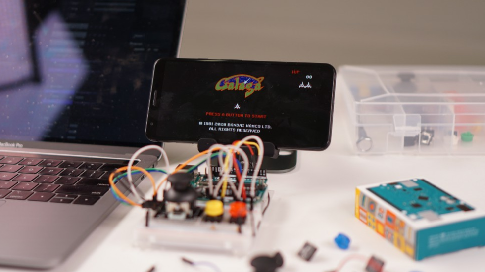
I'll explain below how to build this set-up yourself using a prototype of the old skool game Galaga (I used to play this when I was a kid) that works with a DIY Arduino gamepad.
Note: Arduino usually does involve coding, but in my opinion, you don’t need to go too in-depth with this. So long as the prototype works as you intended it to, that’s sufficient.
Whenever you do need to do some coding, you can find plenty of examples on Google that you can follow.
Set up the Arduino environment
Prepare an Arduino Uno board, one of the most basic and popular boards. It has 6 analog input pins and 14 digital input/output pins. Apart from the Arduino Uno board, the following parts will also be used in this example.
- 1 Breadboard
- 2 Pushbuttons
- 2 Resistors (10kΩ): for pushbuttons
- 1 Joystick module
- 1 Resistor (1kΩ): for joystick
- USB cable (type B to type A): to connect the Arduino board to a laptop
- USB adapter (type A to type C/micro): to connect the Arduino board to an Android device.
- Jumper wires
To assemble the electronic parts, you need a breadboard that’s basically a plastic board with a bunch of pinholes. Pins are connected vertically and horizontally, so there's no need to wire each electronic part end-to-end to make a circuit.
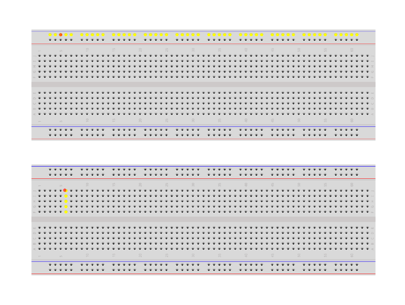
Whenever you use an electronic component like a pushbutton, joystick or LED, you need to put a resistor in the middle of each circuit. This prevents the electronic components from burning out due to overcurrent.
Now, let's connect the parts together using the diagram below and wire them carefully using the jumper wires. You might feel like an electrical engineer when doing this—I certainly do!
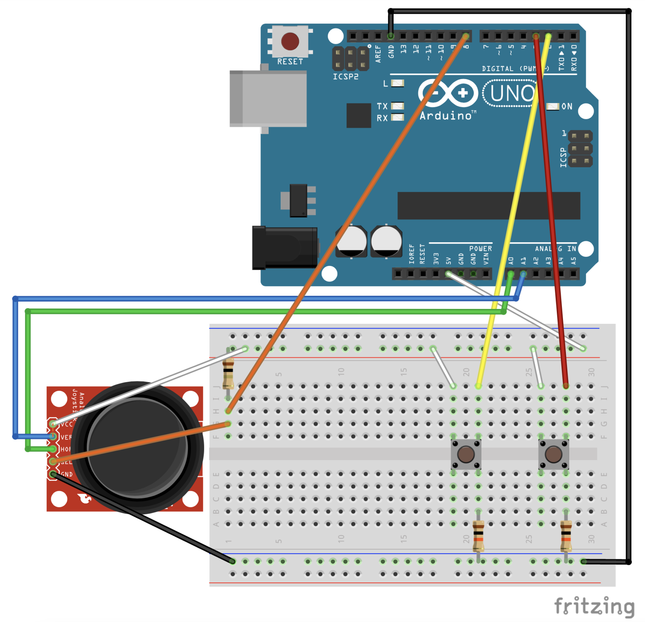
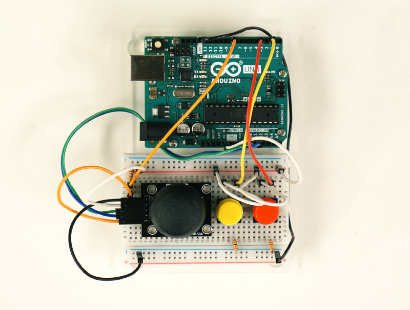
This is how your set-up should look after you've assembled it.
Now, it’s time to switch your electrical engineering hat for a software engineering one. If you want to write and adjust code then you need the Arduino IDE installed on your computer.
Then, copy and paste the code you'll need (shown below.)
#include <PinChangeInterrupt.h>

//Define pins
const int pinA = 2; //A button
const int pinB = 3; //B button

const int X = A0; //Joystick X
const int Y = A1; //Joystic Y
const int Key = 8; //Joystic key button

void sendA() {
  delayMicroseconds(10000); //to avoid chattering effect
  int buttonA = digitalRead(pinA);
  if (buttonA == 1) {
    Serial.println("a"); //Send "a" to ProtoPie
  }
}

void sendB() {
  delayMicroseconds(10000); //to avoid chattering effect
  int buttonB = digitalRead(pinB);
  if (buttonB == 1) {
    Serial.println("b"); //Send "b" to ProtoPie
  }
}


void setup() {
  Serial.begin(9600);

  pinMode(pinA, INPUT);
  pinMode(pinB, INPUT);

  pinMode(Key, INPUT);

  attachInterrupt(digitalPinToInterrupt(pinA), sendA, RISING); //Send a signal once
  attachInterrupt(digitalPinToInterrupt(pinB), sendB, RISING); //Send a signal once

}

void loop() {

  int xVal = analogRead (X);
  int yVal = analogRead (Y);
  int buttonVal = digitalRead (Key);

  if (xVal < 300) {
    Serial.println("left"); //Send "left" to ProtoPie
    delay(500); //Send a signal per 500ms to avoid chatting effect
  }

  if (xVal > 723) {
    Serial.println("right"); //Send "right" to ProtoPie
    delay(500); //Send a signal per 500ms to avoid chatting effect
  }

  if (yVal < 300) {
    Serial.println("up"); //Send "up" to ProtoPie
    delay(500); //Send a signal per 500ms to avoid chatting effect
  }

  if (yVal > 723) {
    Serial.println("down"); //Send "down" to ProtoPie
    delay(500); //Send a signal per 500ms to avoid chatting effect
  }

  if (buttonVal == LOW) {
    Serial.println ("press"); //Send "press" to ProtoPie
    delay(500); //Send a signal per 500ms to avoid chatting effect
  }
}
After hooking up the Arduino board to your computer via a USB cable, upload this sketch (ay code that's run on an Arduino board is called a sketch) to the board. If you want to take a step back and better understand Arduino before you begin, feel free to learn more about the Arduino UNO first.
- Verify your sketch first by going to “Sketch > Verify/Compile”.
- Upload the sketch by going to “Sketch > Upload”.
- After uploading, test if the hardware works properly with the Serial Monitor (“Tools > Serial Monitor”).
- Press the pushbuttons and play around with the joystick to check if signals come in on the monitor window.
Set up the software
Almost done! You now need to install ProtoPie Player on your mobile and ProtoPie Connect on your Desktop (contact us if you want to get ProtoPie Connect). This example works on Android and iOS devices. Learn more about how ProtoPie communicates with Arduino using ProtoPie Connect.
You can download the pie file itself and make adjustments to your own liking using ProtoPie Studio.
Connect Arduino with ProtoPie Player via ProtoPie Connect
1. Use USB cables to connect your laptop, Arduino Uno, and mobile.
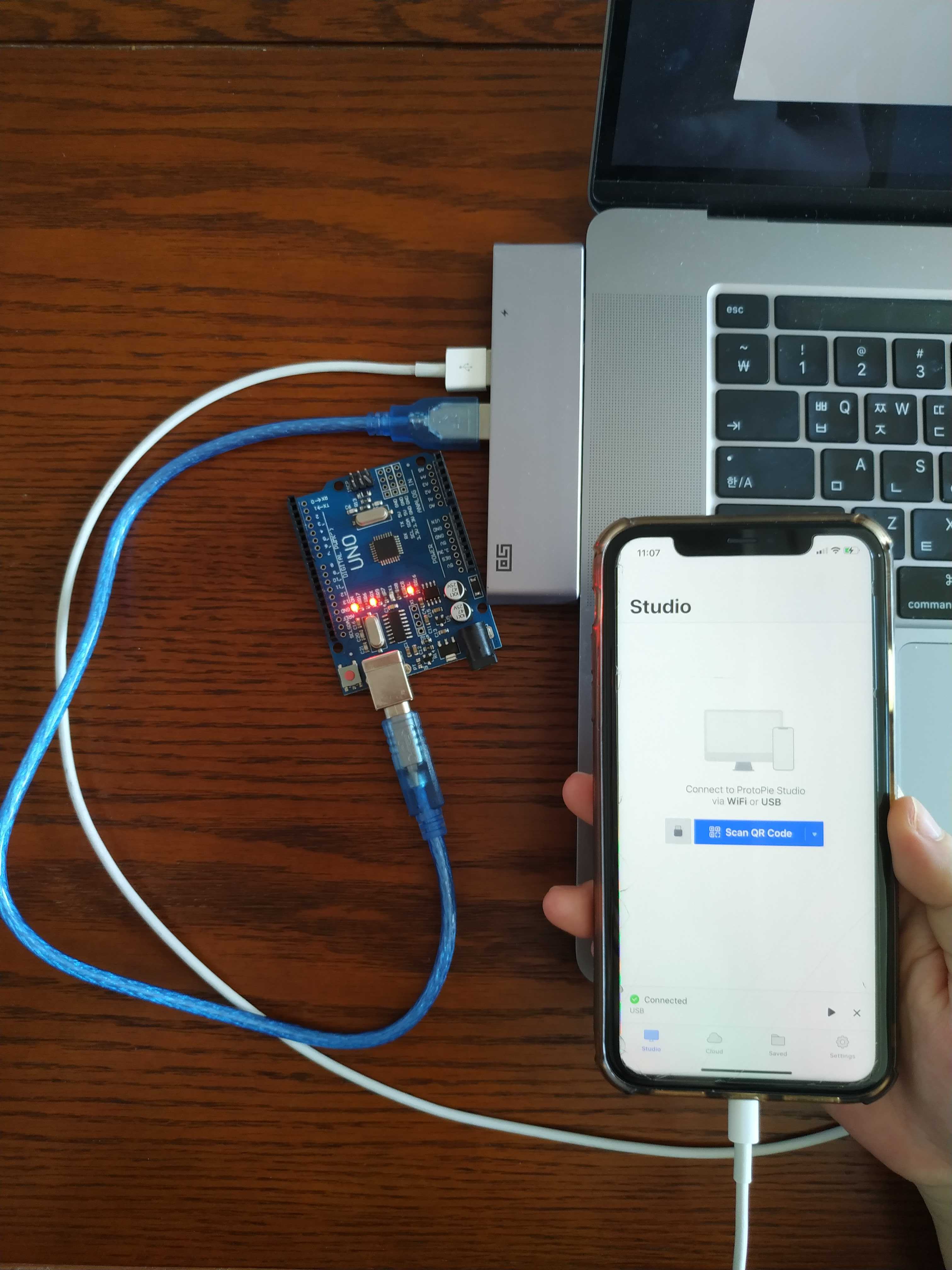
2. Send your Arduino code from Arduino Sketch (Arduino IDE) to Arduino Uno.
3. Connect Arduino with ProtoPie Connect by clicking "..." and then choose USB port and 9600 baud rate.
💡 You cannot connect if the serial monitor is turned on in the Arduino IDE, so first make sure you turn off the serial monitor.
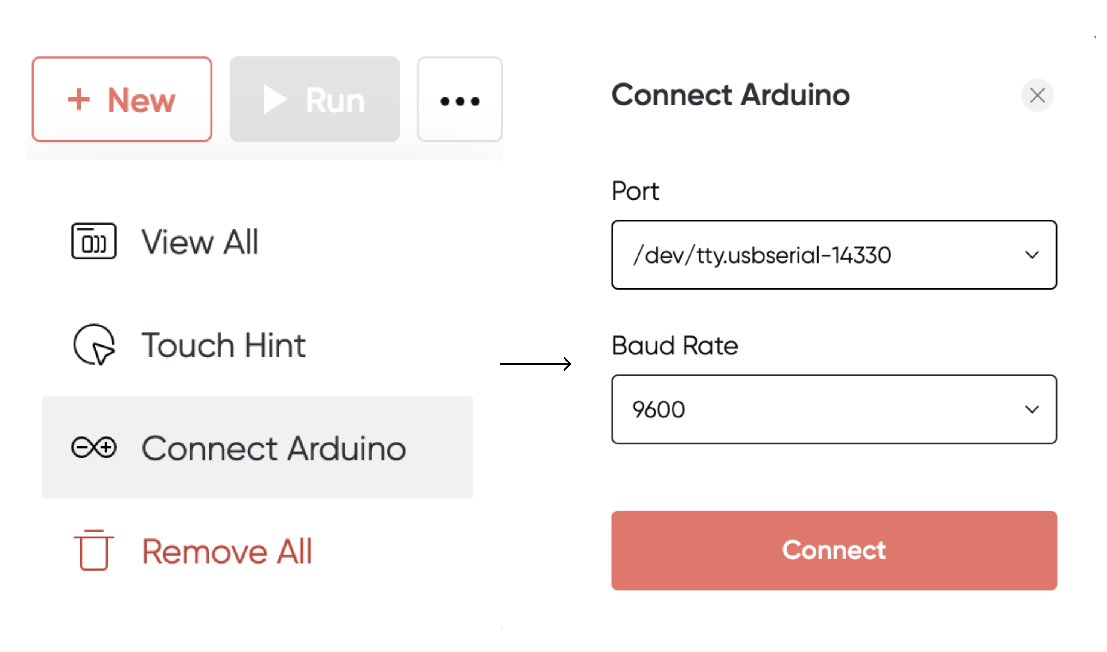
4. Then, click the NEW button to upload the pie file to ProtoPie Connect.
5. The last step is to open ProtoPie Player on your mobile and click the device USB on ProtoPie Connect. You will then see that your prototype has been synced to Player from Connect.
💡 You can also connect ProtoPie Player with ProtoPie Connect via the same wifi network.

Done? Now you’re all set!
You did it!
Congrats! You got your first hardware and software-integrated prototype running successfully.
You might be interested in finding out what else you can prototype using ProtoPie and Arduino. Let me tell you now: the possibilities are endless.
Coding skills shouldn't be a barrier that prevents designers from exploring and validating their ideas. Nor do you have to be an engineer to do this type of prototyping. Mix up your own skills and expertise with whatever insights you can borrow from others. By learning the ropes of how Arduino works with ProtoPie, you can save time and prototype better.
Want to learn more?
- Arduino Project Hub: Explore a ton of awesome projects and use existing sketches.
- Arduino Forum: Ask experts questions.
- Fritzing: Simulate an Arduino board and draw circuit diagrams.
- Arduino Prototyping with ProtoPie: Another article that also covers this topic.
Interested in how I can help you?
My team at ProtoPie and I would love to help you with your prototyping needs—whatever industry you operate in.
If you’re looking for specific prototyping solutions for integrating hardware, software, and APIs for IoT-heavy industries (such as automotive or connected household appliances, among others) then feel free to contact us.
The ProtoPie Automotive Solution
The ProtoPie Automotive Solution is a prototyping solution tailored specifically to the needs of the automotive industry. This allows automotive companies to build and test prototypes across multiple displays while integrating with any hardware and APIs.
The result? Automotive companies can reduce their prototyping cycle and go to market faster and better equipped.
